Camera ↔ LiDAR Calibration Guide
Camera ↔ LiDAR calibration is unique: it represents the intersection of a 2D data format (images) with that of 3D (point clouds). In order to bridge the gap, MetriCal uses the board + circle target. This involves taping a retroreflective circle onto something that can be detected by a camera, like a ChArUco or AprilGrid.
Read more about it in the target guide on combining modalities.
MetriCal doesn't currently calibrate LiDAR intrinsics. If you're interested in calibrating the intrinsics of your LiDAR for better accuracy and precision, get in touch!
Common Camera-LiDAR Workflows
MetriCal offers two approaches to Camera-LiDAR calibration: combined (all-at-once) and staged. The best approach depends on your specific hardware setup and calibration requirements.
Combined Calibration
The combined approach calibrates camera intrinsics and Camera-LiDAR extrinsics simultaneously, which typically yields the most accurate results. This is the approach that we take in the example dataset below.
This approach works best when:
- Your LiDAR and camera(s) can simultaneously view the calibration target
- The circle target can be positioned to fill the camera's field of view
- You have good control over the target positioning
Staged Calibration
For complex rigs where optimal camera calibration and optimal LiDAR-camera calibration require different setups, a staged approach is recommended:
# First stages: Camera-only calibration
[stages.first-init]
command = "init"
dataset = "{{variables.camera-only-dataset}}"
...

[stages.first-calibration]
command = "calibrate"
dataset = "{{variables.camera-only-dataset}}"
input-plex = "{{first-init.initialized-plex}}"
...

# Second stages: Camera-lidar calibration with
# referenced camera intrinsics from first stages
[stages.second-init]
command = "init"
dataset = "{{variables.camera-lidar-dataset}}"
# >>> Use camera cal from first stages <<<
reference-source = ["{{first-calibration.results}}"]
...

[stages.second-calibration]
command = "calibrate"
dataset = "{{variables.camera-lidar-dataset}}"
input-plex = "{{second-init.initialized-plex}}"
...
# This will now have all intrinsics + extrinsics
results = "{{auto}}"
This staged approach allows you to capture optimal data for camera intrinsics in one dataset, getting close to ensure full FOV coverage, and then use a different dataset optimized for Camera-LiDAR extrinsics in the second stage.
The staged approach is particularly useful when:
- Your camera is mounted in a hard-to-reach position
- You need different viewing distances for optimal camera calibration vs. LiDAR-camera calibration
- You're calibrating a complex rig with multiple sensors
For tips on getting a great camera calibration, see the Single Camera Calibration guide and the Multi-Camera Calibration guide.
Example Dataset and Manifest
We've captured an example of a good LiDAR ↔ Camera calibration dataset that you can use to test out MetriCal. If it's your first time performing a LiDAR calibration using MetriCal, it might be worth running through this dataset once just so that you can get a sense of what good data capture looks like.
This dataset features:
- Observations as a folder of folders
- Two infrared cameras
- One LiDAR
- One Camera-LiDAR multi-modal target
The Manifest
[project]
name = "MetriCal Demo: Camera LiDAR VA Pipeline"
version = "15.0.0"
description = "Manifest for running MetriCal on a camera-lidar dataset"
workspace = "metrical-results"

## === VARIABLES ===
[project.variables.dataset]
description = "Path to the input dataset containing camera and lidar data."
value = "camera_lidar_va_observations/"

[project.variables.object-space]
description = "Path to the input object space JSON file."
value = "camera_lidar_va_objects.json"

## === STAGES ===
[stages.cam-lidar-init]
command = "init"
dataset = "{{variables.dataset}}"
reference-source = []
topic-to-model = [["*infra*", "no-distortion"], ["velodyne_points", "lidar"]]
... # ...more options...
initialized-plex = "{{auto}}"

[stages.cam-lidar-calibrate]
command = "calibrate"
dataset = "{{variables.dataset}}"
input-plex = "{{ cam-lidar-init.initialized-plex }}"
input-object-space = "{{variables.object-space}}"
camera-motion-threshold = "disabled"
lidar-motion-threshold = "strict"
render = true
... # ...more options...
detections = "{{auto}}"
results = "{{auto}}"
Let's take a look at some of the important details of this manifest:
- Our first stage, the Init command, is assigning all topics that match the
*infra*pattern to theno-distortionmodel. This is a convenient way to assign models to topics without needing to know the exact topic names ahead of time. Don't worry: MetriCal will yell at you if you have conflicting topics that match the same pattern. - Our second stage, the Calibrate command, has a
disabledcamera motion threshold, but astrictlidar motion threshold. This is a good way to handle datasets outside or in a parking lot, where there might be a lot of intensely reflective surfaces that could cause spurious LiDAR detections. - Our second stage is rendered! This flag will allow us to watch the detection phase of the calibration as it happens in real time. This can have a large impact on performance, but is invaluable for debugging data quality issues.
MetriCal depends on Rerun for all of its rendering. As such, you'll need a specific version of Rerun
installed on your machine to use the --render flag. Please ensure that you've followed the
visualization configuration instructions before running this
manifest.
Running the Manifest
With a copy of the dataset downloaded and the manifest file created, you should be ready to roll:
metrical run camera_lidar_va_manifest.toml
Immediately, MetriCal will open a visualization window like the following with a LiDAR point cloud and detections overlaid on the camera frames. Note that the LiDAR circle detections will show up as red points in the point cloud.
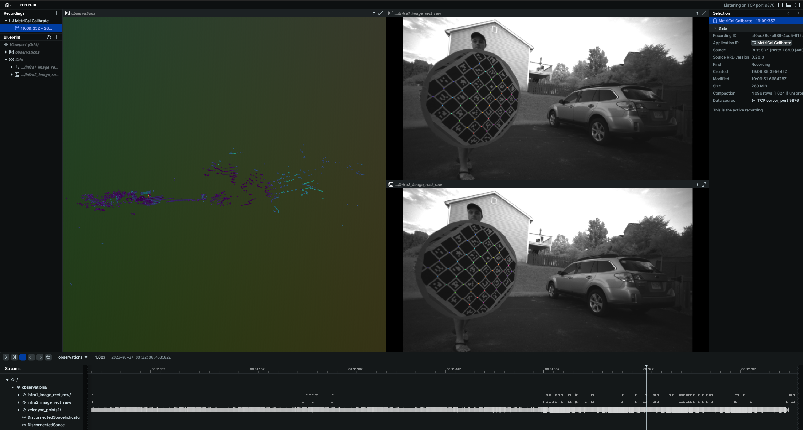
While the calibration is running, take specific note of the target motion patterns, presence of still periods, and breadth of camera coverage. When it comes time to design a motion sequence for your own systems, try to apply any learnings you take from watching this capture.
When the run finishes, you'll be left with three artifacts:
initialized-plex.json: Our initialized plex from the first stage.report.html: a human-readable summary of the calibration run. Everything in the report is also logged to your console in realtime during the calibration. You can learn more about interpreting the report here.results.mcap: a file containing the final calibration and various other metrics. You can learn more about results here and about manipulating your results usingshapecommands here.
Residual Metrics
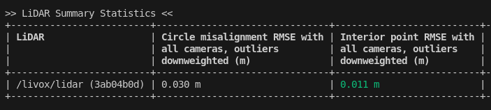
For camera-LiDAR calibration, MetriCal outputs two key metrics:
-
Circle misalignment RMSE: Indicates how well the center of the markerboard (detected in camera space) aligns with the geometric center of the retroreflective circle (in LiDAR space). Typically, values around 3cm or less indicate a good calibration.
-
Interior point-to-plane RMSE (if
detect_interior_pointswas enabled): Measures how well the interior points of the circle align with the plane of the circle. Values around 1cm or less are considered good.
Visualizing Results
You can focus on LiDAR detections by double-clicking on detections in the Rerun interface
To see the aligned camera-LiDAR view, double-click on a camera in the corrections space:
If the calibration quality doesn't meet your requirements, consider recapturing data at a slower pace or modifying the target with more/less retroreflectivity.
Data Capture Guidelines
LiDAR ↔ Camera calibrations are currently an extrinsics-only calibration. Note that while we only solve for the extrinsics between the LiDAR and the camera components, the calibration is still a joint calibration as camera intrinsics are still estimated as well.
Best Practices
| DO | DON'T |
|---|---|
| ✅ Vary distance from sensors to target a few times to capture a wider range of readings. | ❌ Stand at a single distance from the sensors. |
| ✅ Make sure some of your captures fill much of the camera field of view. | ❌ Only capture poses where the target does not capture much of the cameras' fields of view. |
| ✅ Rotate the target on its planar axis periodically to capture poses of the board at different orientations. | ❌ Keep the board in a single orientation for every pose. |
| ✅ Maximize convergence angles by occasionally angling the target up/down and left/right during poses. | ❌ Keep the target in a single orientation, thereby minimizing convergence angles. |
| ✅ Pause in between poses to eliminate motion blur effects. | ❌ Move the target constantly or rapidly during data capture. |
| ✅ Bring the target close to each camera lens and capture target poses across each camera's entire field of view. | ❌ Stay distant from the cameras or only capture poses that cover part of each camera's field of view. |
| ✅ Achieve convergence angles of 35° or more on each axis. |
Maximize Variation Across All 6 Degrees Of Freedom
When capturing the circular target with your camera and LiDAR components, ensure that the target can be seen from a variety of poses by varying:
- Roll, pitch, and yaw rotations of the target relative to the sensors
- X, Y, and Z translations between poses
MetriCal performs LiDAR-based calibrations best when the target can be seen from a range of different depths. Try moving forward and away from the target in addition to moving laterally relative to the sensors.
Pause Between Different Poses
MetriCal performs more consistently if there is less motion blur or motion-based artifacts in the captured data. For the best calibrations, pause for 1-2 seconds after every pose of the board. Constant motion in a dataset will typically yield poor results.
Advanced Considerations
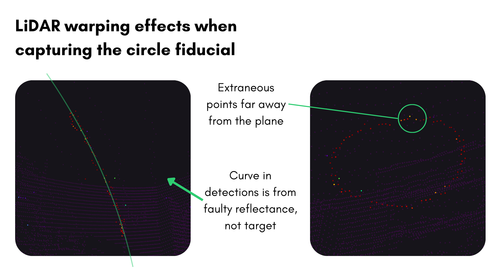
Beware of LiDAR Noise
Some LiDAR sensors can have significant noise when detecting retroreflective surfaces. This can cause a warping effect in the point cloud data, where points are spread out in a way that makes it difficult to detect the true surface of the circle.
For Ouster LiDARs, this is caused by the retroreflective material saturating the photodiodes and
affecting the time-of-flight estimation. To prevent this warping effect, you can lower the signal
strength of the emitted beam by sending a POST request and modifying the signal_multiplier to
0.25 as shown in the
Ouster documentation.
Troubleshooting
If you encounter errors during calibration, please refer to our Errors and Troubleshooting documentation.
Remember that all measurements for your targets should be in meters, and you should ensure visibility of as much of the target as possible when collecting data.