System Specification
A system specification is a JSON file that encodes mechanical and optical knowledge about your sensor system, i.e. things you would typically find in a CAD model or a sensor datasheet. It lets you seed a Plex with informed initial guesses before calibration, rather than relying entirely on data-driven inference.
A system specification captures three kinds of information:
- Mechanical layout: the spatial transforms (translation + rotation) between pairs of sensors, based on CAD measurements or mechanical drawings.
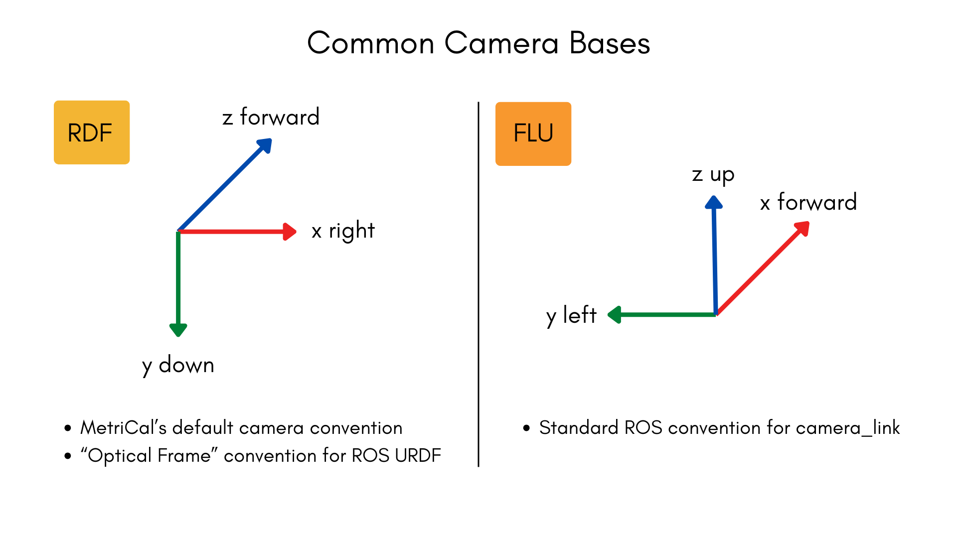
- Camera coordinate bases: the convention each camera uses for its 3D coordinate frame (e.g.,
"FLU"for Forward-Left-Up or"RDF"for Right-Down-Forward). - Camera field of view: the nominal diagonal field of view (DFoV) of each camera in degrees, typically from a datasheet.
Why Use a System Specification?
When MetriCal learns a Plex from a dataset alone, it must infer spatial relationships and intrinsic estimates purely from the data. This works well in many cases, but providing a system specification offers several advantages:
- Better initial extrinsics: Mechanical measurements from CAD are often more accurate starting points, leading to faster and more reliable convergence during calibration.
- Focal length seeding: Providing a nominal DFoV allows MetriCal to compute a reasonable initial focal length estimate; this is especially helpful for cameras with narrow or telescopic fields of view.
- Basis correction: If your mechanical layout assumes a camera coordinate convention other than RDF (Right-Down-Forward), the system specification tells MetriCal how to interpret those extrinsics correctly.
- Spec-only plexes: You can create a Plex from a system specification alone (without any dataset), useful for pre-configuring a system before data is available.
JSON Format
A system specification file is written in JSON. Comments are supported; MetriCal strips them before
parsing. All three top-level keys are optional; you can include only the ones relevant to your
system. An empty object {} is a valid (though not useful) system specification.
{
    // Camera coordinate basis conventions
    "camera_bases": {
        "/camera/front": "FLU",
        "/camera/rear": "FRD"
    },

    // Nominal diagonal field of view per camera, in degrees
    "camera_field_of_view": {
        "/camera/front": 90.0,
        "/camera/rear": 120.0
    },

    // Mechanical extrinsics between sensor pairs
    "mechanical_layout": [
        {
            "from": "/lidar/top",
            "to": "/camera/front",
            "translation": [0.05, 0.0, -0.12],
            "rotation": { "unit_quaternion": [0.0, 0.0, 0.0, 1.0] }
        }
    ],
    // Base and end effector frames of a transform tree
    "transform_tree_frames": {
        "/tf": {
            "base_frame": "base_link",
            "tool_frame": "tool0",
            "mount_type": "eye-in-hand"
        }
    }
}
camera_bases
A map from topic name to a three-character coordinate basis string. Each character represents the
direction of the X, Y, and Z axes respectively, using the letters U (Up), D (Down), L (Left),
R (Right), F (Forward), and B (Backward).
The basis must be right-handed and orthogonal. There are 24 valid bases:
ULB,URF,UFL,UBR,DLF,DRB,DFR,DBL,LUF,LDB,LFD,LBU,RUB,RDF,RFU,RBD,FUR,FDL,FLU,FRD,BUL,BDR,BLD,BRU
MetriCal works internally in the RDF convention (X-Right, Y-Down, Z-Forward). If a camera is listed in this map with a different basis, MetriCal will apply a change-of-basis correction to any spatial constraints involving that camera so that the extrinsics are consistent in the internal RDF frame. Cameras not listed in this map default to RDF.
Only cameras need a basis entry because they are the only component type with ambiguous coordinate conventions. All other component types (LiDARs, IMUs, local navigation systems) use canonical right-handed XYZ axes, so MetriCal can interpret their frames without additional configuration.
camera_field_of_view
A map from topic name to the camera's diagonal field of view in degrees. The value must be a positive, finite number. Values exceeding 360 degrees are normalized to the range [0, 360).
MetriCal uses the DFoV together with the camera's image dimensions to compute an initial focal length estimate. This seeds the camera's intrinsics with a more realistic starting point than the default, which can improve calibration convergence.
Providing a DFoV is most helpful when the camera's field of view differs significantly from a "typical" pinhole camera. Narrow and telescopic lenses in particular benefit from an informed focal length seed, since their geometry makes data-driven initialization less reliable.
mechanical_layout
An array of directional extrinsic entries, each describing the spatial transform from one sensor to another. Every entry has four fields:
| Field | Type | Description |
|---|---|---|
from | String | The topic name of the source sensor (the coordinate frame you are transforming from). |
to | String | The topic name of the destination sensor (the coordinate frame you are transforming into). |
translation | [X, Y, Z] | Translation in meters, as a 3-element array. |
rotation | Object | Rotation; either a unit_quaternion or a matrix (see below). |
transform_tree_frames
Identifies the base and end effector frames per relevant transform tree topic. This data is used during a hand-eye calibration to solve for the proper constraint. Every transform tree specified has three fields:
| Field | Type | Description |
|---|---|---|
base_frame | String | The name of the base frame of the robotic arm. |
tool_frame | String | The name of the end effector frame of the robotic arm. |
mount_type | eye-to-hand | The type of hand-eye system MetriCal should expect. |
Rotation formats
The rotation field accepts one of two representations:
Unit quaternion (recommended for most users):
{ "unit_quaternion": [xi, yj, zk, w] }
The quaternion is specified in [x, y, z, w] order and will be automatically normalized if it is
not already unit-length.
Column-major rotation matrix (for users with DCM data from CAD):
{ "matrix": [[col0_x, col0_y, col0_z], [col1_x, col1_y, col1_z], [col2_x, col2_y, col2_z]] }
Each inner array is one column of the 3x3 directional cosines matrix. The columns will be automatically normalized.
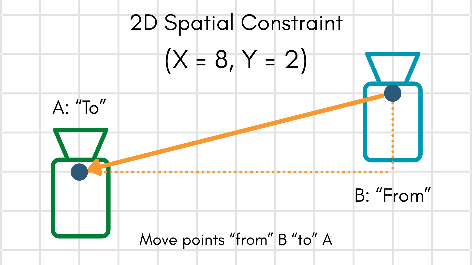
Extrinsics convention
The transform convention follows MetriCal's standard "to-from-from" convention, the same one used by
spatial constraints. Given a point in the from frame,
applying the extrinsic moves it into the to frame:
How Plex Learn Uses the System Specification
When you pass a system specification to
metrical plex learn via the
-S/--system-specification flag, the following steps occur:
- Focal length seeding: For each camera that has a
camera_field_of_viewentry, MetriCal computes an initial focal length from the DFoV and the camera's image dimensions, then updates the camera's intrinsics. - Extrinsics replacement: For each sensor pair in the
mechanical_layoutthat corresponds to an existing spatial constraint in the Plex, MetriCal replaces the constraint's extrinsics with the mechanical layout values. - Basis correction: If any cameras involved in a spatial constraint have a non-RDF basis listed
in
camera_bases, MetriCal rotates the extrinsics so that you do not need to pre-transform your mechanical layout into MetriCal's internal RDF convention. - Persistence: The system specification is stored on the output Plex and propagated through
subsequent
calibrateandshapestages. - Hand-Eye Systems: Since hand-eye calibrations involve a separate moving frame, the system spec identifies that frame on behalf of MetriCal. This is done here, rather than the plex, because the transform should be common to all systems (assuming a consistent workflow).
The system specification is applied after any data-driven learning from the dataset. This means system specification values take precedence over values inferred from data, on the assumption that mechanical measurements from CAD are more trustworthy than naive data-driven estimates.
Creating a System Specification
MetriCal provides two commands for creating system specification files:
metrical spec newscaffolds an annotated JSONC template with example values and comments explaining each field. This is the easiest way to start from scratch.metrical spec from-urdfconverts a ROS URDF file into a system specification, extracting fixed-joint transforms and optionally setting camera properties. This is useful when your sensor rig is already described in a URDF. See Using a URDF as a System Specification for a step-by-step walkthrough.
You can also write the JSON by hand using the format described above.
Examples
Camera-only system with FLU cameras
A system with two cameras that use the FLU (Forward-Left-Up) convention, with known fields of view and a known mechanical offset between them:
{
    "camera_bases": {
        "/camera/left": "FLU",
        "/camera/right": "FLU"
    },
    "camera_field_of_view": {
        "/camera/left": 90.0,
        "/camera/right": 90.0
    },
    "mechanical_layout": [
        {
            "from": "/camera/left",
            "to": "/camera/right",
            "translation": [0.12, 0.0, 0.0],
            "rotation": { "unit_quaternion": [0.0, 0.0, 0.0, 1.0] }
        }
    ]
}
Camera-LiDAR system
A system with one camera and one LiDAR, where the LiDAR is mounted above and behind the camera. The
camera uses the default RDF convention, so it does not need a camera_bases entry:
{
    "camera_bases": {},
    "camera_field_of_view": {
        "/camera/front": 70.0
    },
    "mechanical_layout": [
        {
            "from": "/lidar/top",
            "to": "/camera/front",
            "translation": [0.0, -0.15, -0.1],
            "rotation": { "unit_quaternion": [0.0, 0.0, 0.0, 1.0] }
        }
    ]
}
Multi-sensor rig with rotation matrix
A more complex system using a rotation matrix (DCM) for one of the transforms:
{
    "camera_bases": {
        "/camera/front": "FRD"
    },
    "camera_field_of_view": {
        "/camera/front": 110.0
    },
    "mechanical_layout": [
        {
            "from": "/imu/main",
            "to": "/camera/front",
            "translation": [0.05, 0.02, -0.03],
            "rotation": {
                "matrix": [
                    [1.0, 0.0, 0.0],
                    [0.0, 0.0, -1.0],
                    [0.0, 1.0, 0.0]
                ]
            }
        },
        {
            "from": "/imu/main",
            "to": "/lidar/top",
            "translation": [0.0, 0.0, 0.3],
            "rotation": { "unit_quaternion": [0.0, 0.0, 0.0, 1.0] }
        }
    ]
}
Minimal spec (field of view only)
If you only want to seed focal lengths and have no mechanical layout or basis information to provide, you can leave the other fields empty:
{
    "camera_bases": {},
    "camera_field_of_view": {
        "/camera/wide": 150.0,
        "/camera/tele": 30.0
    },
    "mechanical_layout": []
}