Camera Data Capture
MetriCal's camera calibration is a joint process, which includes calibrating intrinsics and extrinsics at the same time. We provide some tips and tricks below for capturing data for camera calibrations, so as to make it easier to produce consistent and environment-agnostic results.
Guidelines for Individual Camera Calibration
Tutorial Video
Watch the video below for a quick overview of the guidelines for individual camera calibration:
Keep Targets in Focus
This tip is an absolute must when capturing data with cameras. Data that is captured out-of-focus breaks underlying assumptions that are made about the relationship between the image projection and object space; this, in turn, breaks the projection model entirely!
A lens focused at infinity captures objects far away with ease without defocusing, so this is the recommended setting for calibration. Care should be taken, therefore, not to get a target too close to a lens that it blurs out the image. This near-to-far range in which objects are still focused is called a camera's depth of field. Knowing your depth of field can ensure you never get a blurry image in your data.
It should be noted that a lens with a shorter focal length, i.e. wide field of view, tends to stay in focus over larger depths of field.
Consider Your Target Orientations
One of the largest sources of projective compensation comes from and correlations in the image space observations. Just to give you an idea of how connected these parameters are:
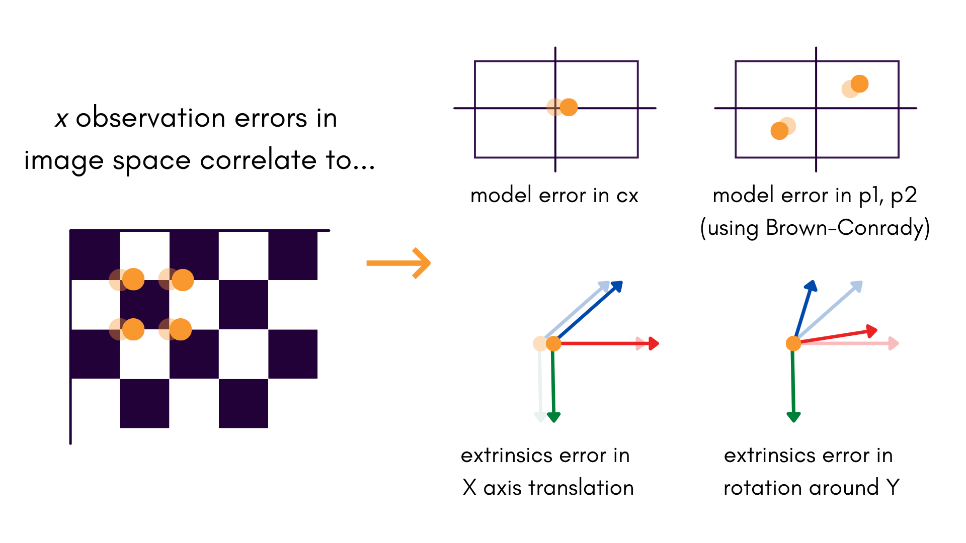
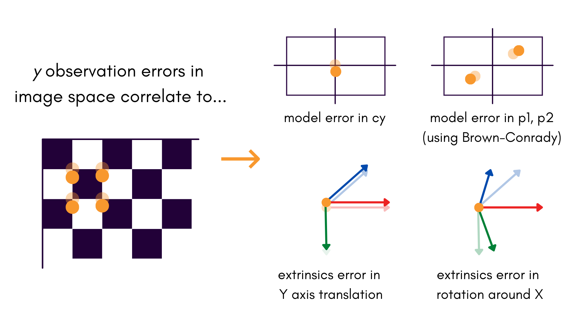
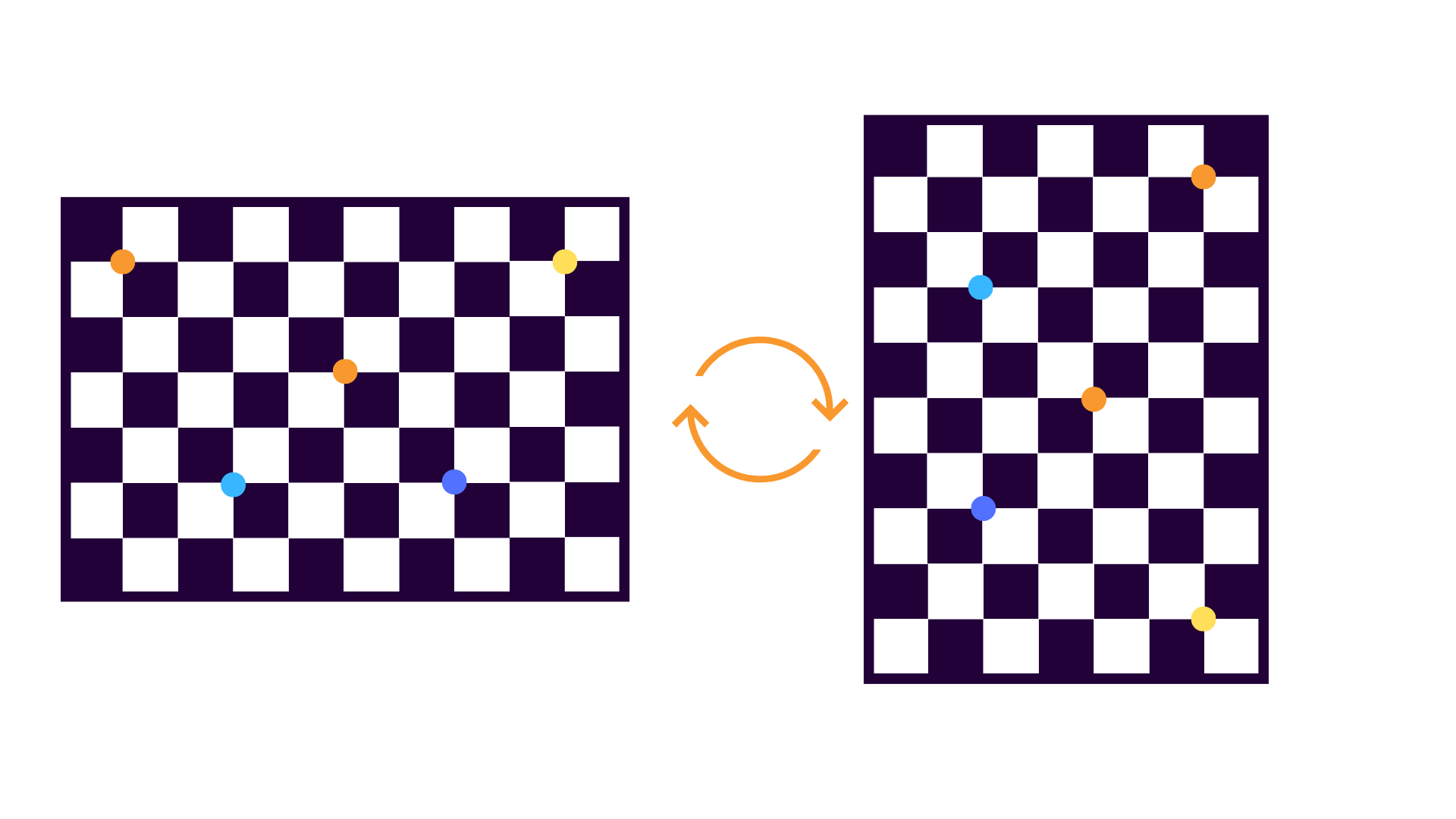
All of these effects are especially noticeable when there is little to no depth variation in the target field. Even if it is not possible to change the object space to include some depth variation, it is almost always helpful to collect data where the target field is collected at 0° and 90° orientations:
When the object space is captured at 0°:
- image measurements directly measure in object space
- image measurements directly measure in object space
When the object space is captured at 90°:
- image measurements directly measure in object space
- image measurements directly measure in object space
This process de-correlates errors in and , because small errors in the and image measurements are statistically independent. There is no need to collect more data beyond 0° and 90° rotations; the two orientations alone do enough.
Note that the same trick can be applied if the target is static, and the camera is rotated relative to the targets instead.
Rotating your target is an easy step which can help reduce a lot of projective compensations in the final calibration result, leading to a more stable and consistent calibration process.
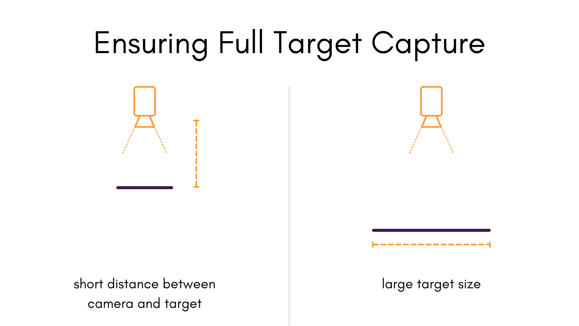
Consider the Full Field Of View
tl;dr: the bigger the target is in the image, the better.
A common data capture mistake is to only place the target in a small part of the field of view of the camera. This makes it extremely difficult to model radial distortions, especially if the majority of the data is in the center of the extent of the image. To mitigate this, object points should be observed across as much of the camera's field of view as is possible.
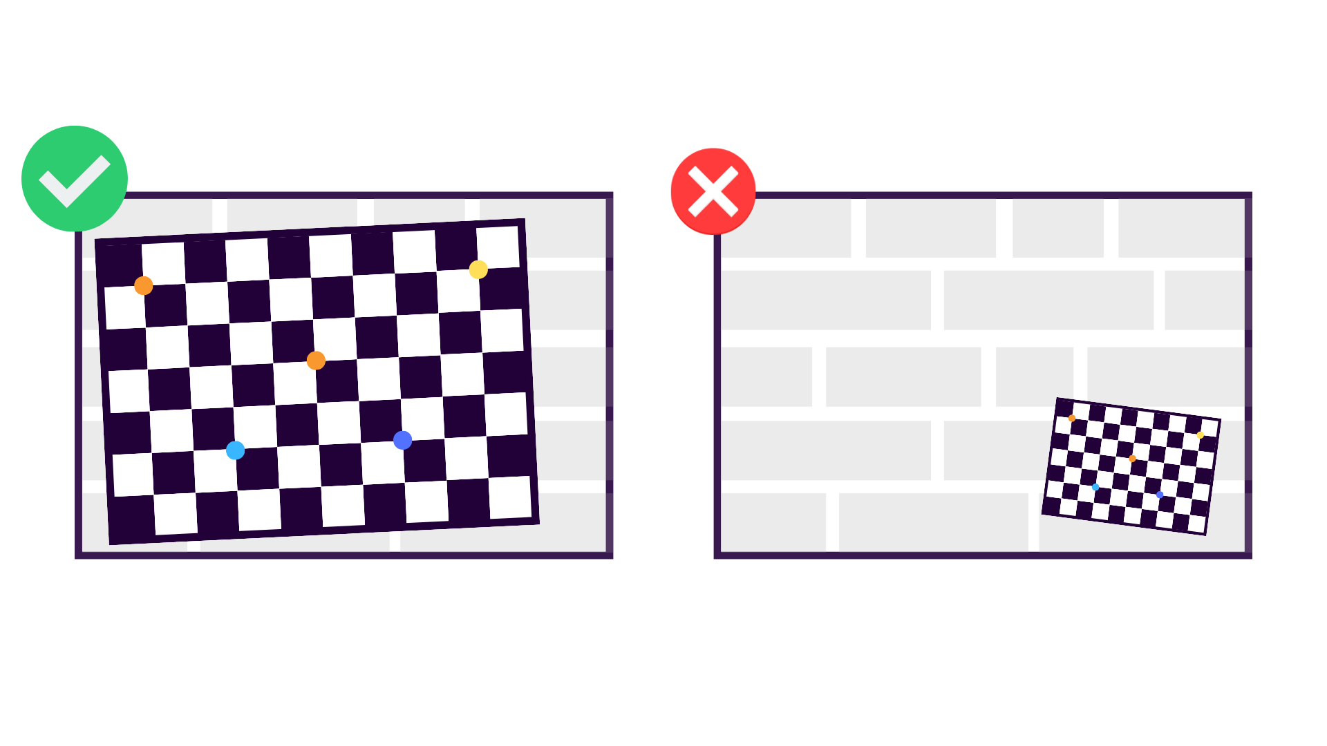
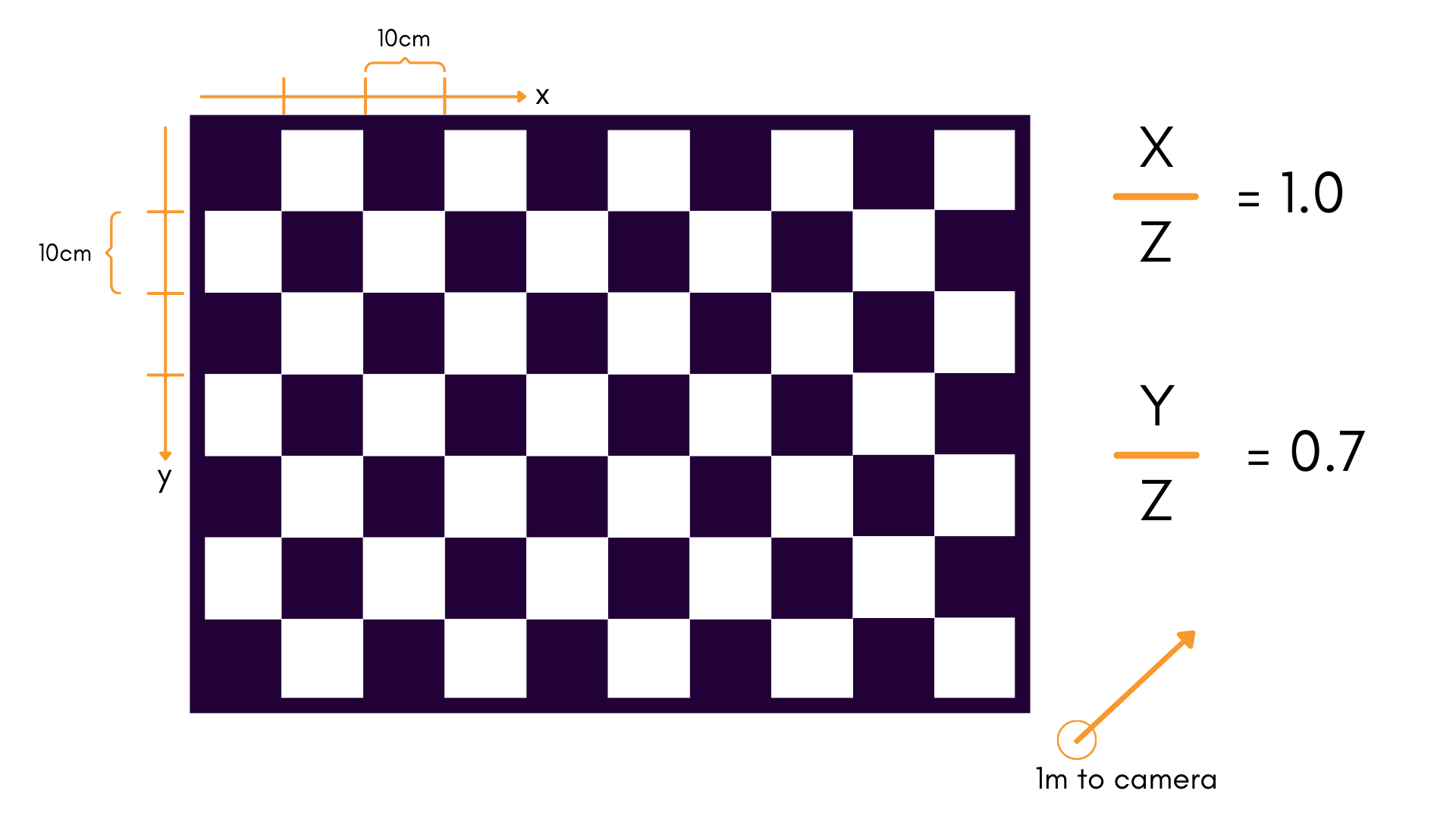
It is especially important to get image observations with targets near the periphery of the image, because this where distortion is the greatest, and where it needs to be characterized the best. We can get a better intution for why this is by looking at the basic projection model of our cameras:
See our projection page for a breakdown of this model.
When calibrating this model, the ratio of the target field's width compared to the distance to the target field is an important limiting factor in how observable our projection model is. The same logic applies to the ratio of to .
We especially want to avoid scenarios where these ratios are small. As a good rule-of-thumb, a ratio of about 1:1 is a good starting point. For a standard 10x7 checkerboard, this would mean:
- 10 squares in the -direction, each of length 0.10m
- 7 squares in the -direction of length 0.10m
- Held 1m away from the camera during data collection
This gives a ratio of 1:1 in , and 7:10 in .
In general, increasing the size of the target field is preferred to moving too close to the camera (see "Keep Targets In Focus" above). However, both can be useful in practice.
Maximize the Convergence Angle
The convergence angle of the camera's pose relative to the object space is a major factor in the determination of our focal length , among other parameters. The more the angle changes in a single dataset, the better; In most scenarios, reaching a convergence angle of 70° or greater is recommended.
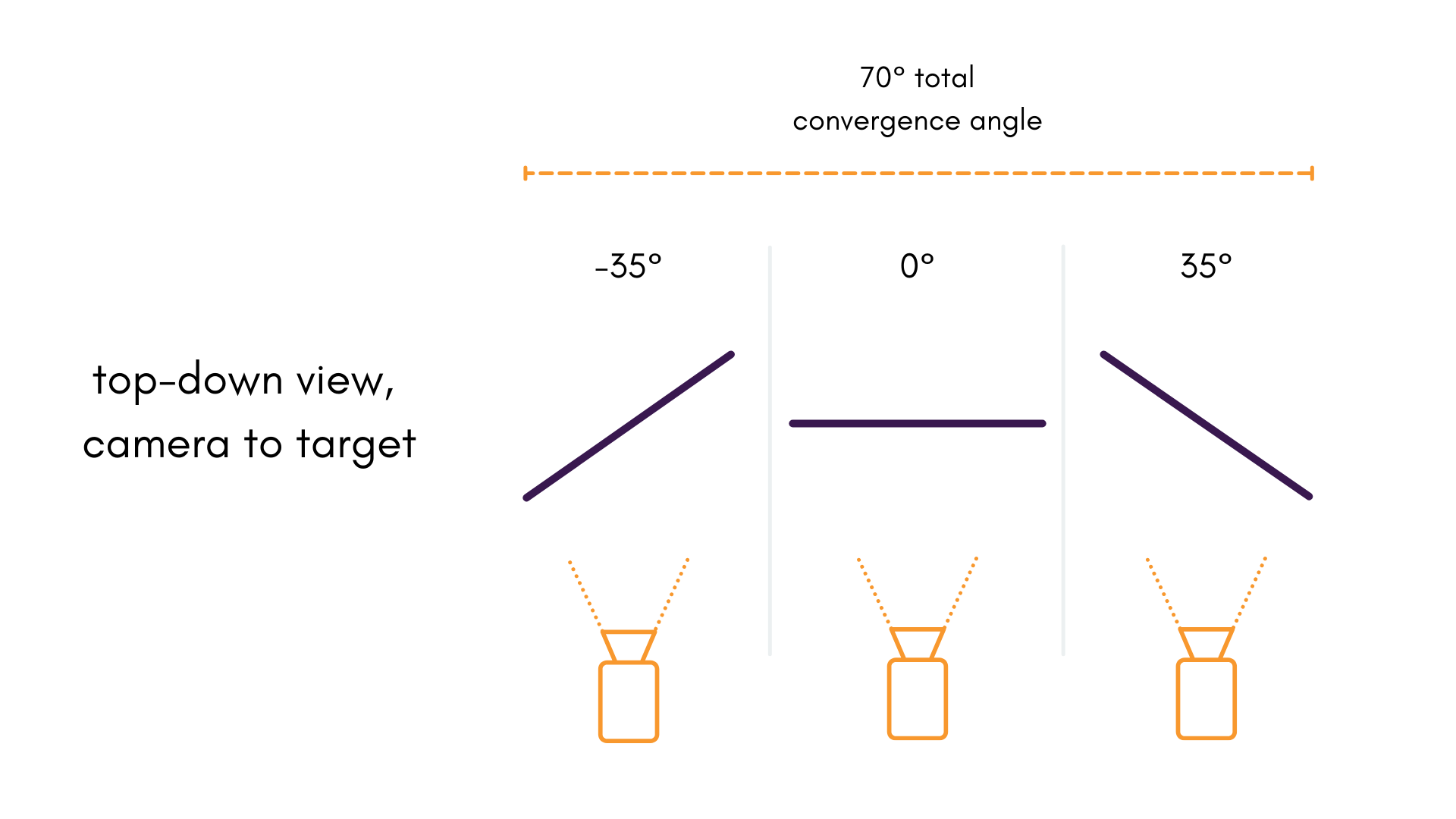
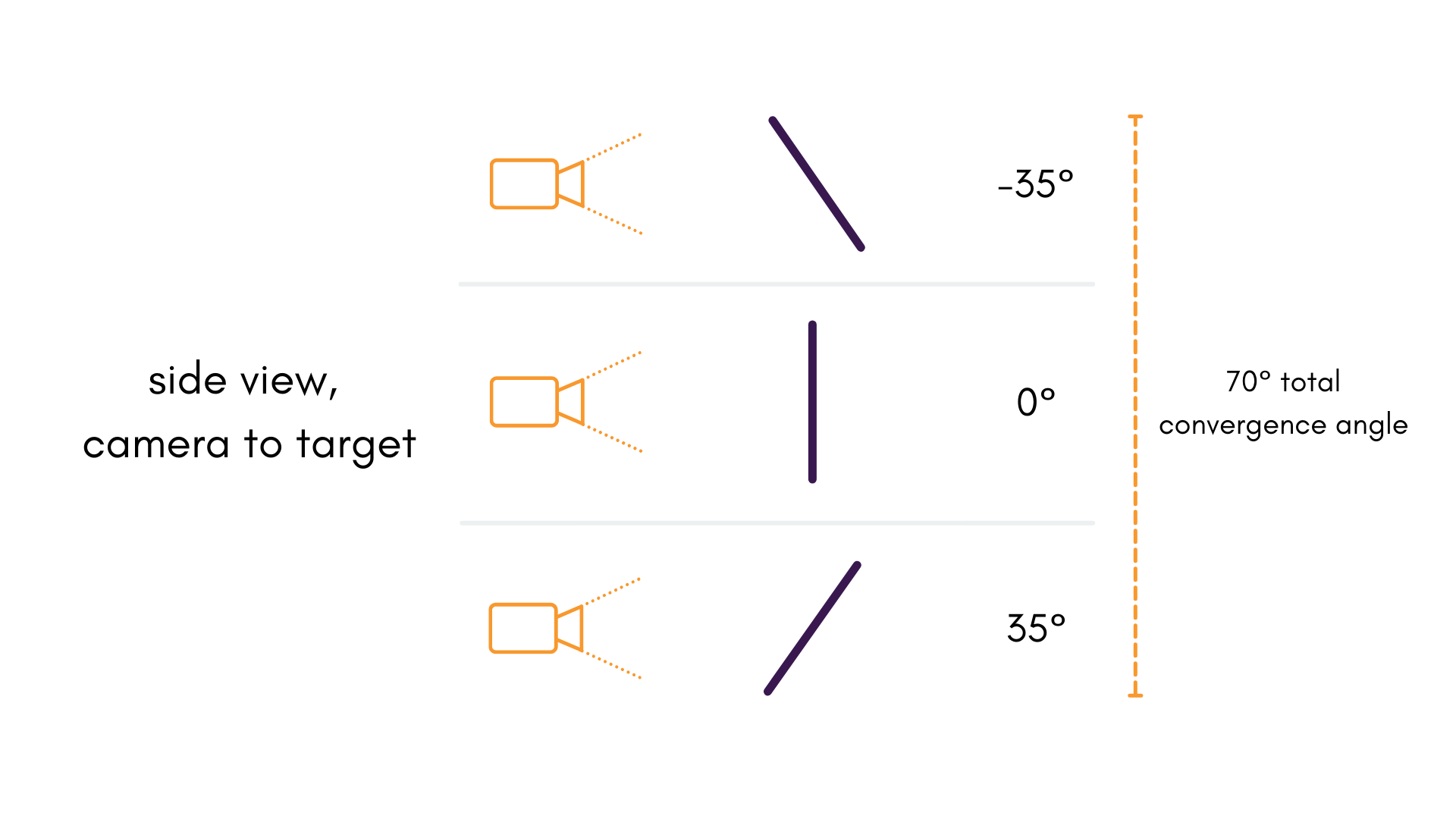
It is worth noting that other data qualities shouldn't be sacrificed for better angles. it is still important for the image to be in focus and for the targets to be observable.
Guidelines for Multi-Camera Calibration
Maximize Overlap Between Images
Filling the full field-of-view of the image is an important consideration for each camera individually because of how it postively influences the determination of distortions in the frame. Conversely, it isn't enough to just fill the field-of-view when capturing multi-camera data, as camera components need to jointly observe the same object space (or object spaces) in order to determine the relative extrinsics between the two cameras.
Once you feel that you've observed across the entire field-of-view of each camera individually, it can be a good idea to try and observe the object space in multiple cameras from the same position.
It is important to consider that where this overlap is present can be a matter of importance in this image. For example, when working with very-wide field-of-view lenses having overlap only at the peripheries can sometimes produce odd results, because the overlap is largely contained in high distortion areas of the image.
Using Multiple Object Spaces
The Importance of Depth Variation
This point is more of a consideration than a requirement. At the very least, it should serve to provide you with more intuition about the calibration data capture process.
Using a single, flat planar targets like the ones discussed above, provide very little variation in object space depth . Restricting object space to a single plane in this way introduces projective compensation in all sorts of ways:
- to all object space coordinates
- and to both and extrinsic rotations about and (for Brown-Conrady)
- to through (for Kannala-Brandt)
A non-planar target, or a combination of targets using multiple object spaces helps to mitigate this effect by adding depth variation in . In general, more depth variation is better. Admittedly, a non-planar target can complicate data capture, and manufacturing and transporting these target types can be a chore. If you have one, though, it provides advantages over its planar counterparts.
For those with only a single, planar calibration targets — know that MetriCal can still give great calibration results given the other data capture guidelines are followed.